1. Scope: This manual applies to electric (or pneumatic) ball valves at the flange connection end.
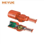
2. Composition: It is composed of an electric (or pneumatic) actuator and a ball valve body, which is connected by the bracket and the connecting shaft.
3. Restrictions on Use
1) Temperature and pressure limits
2) The nameplate shows the maximum allowable operating pressure of the ball valve at the maximum and minimum operating temperatures.
3) Using PTFE or RTFE valve seats and seals, the operating temperature should be between 150 degrees and 200 degrees. The operating temperature of other types of valve seats and seals should be checked.
4) The nominal pressure rating (PN) of the cryogenic valve, which indicates the maximum working pressure of the valve at normal temperature conditions. (For example: PN4.0, indicating that its maximum working pressure at -290C~380C is 40 bar (4.0MPa)).
5) Precautions for electric or pneumatic actuators refer to their corresponding instructions.
4. Installation
1) Remove the protective covers on both sides of the flange end and rinse and clean when the valve is fully open.
2) Before installation, the whole machine should be tested according to the specified signal (electricity or gas) (to prevent vibration due to transportation from affecting the use performance), and it can be installed online only after passing (wiring according to the circuit diagram of the electric actuator).
3) Before preparing to connect with the pipe, rinse and remove the remaining impurities in the pipe (these substances may damage the valve seat and ball).
4) During installation, please do not use the actuator part of the valve as the lifting point to avoid damage to the actuator and accessories.
5) This type of valve should be installed in the horizontal or vertical direction of the pipeline.
6) The pipeline near the installation point should not have low hanging or withstand external force, and the pipeline bracket or support can be used to eliminate the deviation of the pipeline.
7) After connecting with the pipeline, please use the specified torque cross-lock flange to connect the bolts.
5. Operation and use
1) Before operation, confirm that the pipeline and valve have been flushed.
2) The operation of the valve is completed by driving the rotation of the valve stem according to the size of the input signal of the actuator: when the positive rotation is 1/4 turn (90°), the valve is closed. When the reverse rotation is 1/4 turn (90°), the valve opens.
3) When the direction indication arrow of the actuator is parallel to the pipeline, the valve is open; When the indicator arrow is perpendicular to the line, the valve is closed.
6. Maintenance
A long service life and maintenance-free period will depend on several factors: normal operating conditions, maintaining a harmonious temperature/pressure ratio, and reasonable corrosion data.